Flasher - Troubleshooting
The connection to a Flasher or the target device may not work for a variety of reasons.
The following article provides information on how to troubleshoot and fix these connectivity issues.
Generic
- Make sure to use the most recent version of the Flasher software, available for download here.
- Make sure that Flasher is running its most recent firmware version. For more information on Flasher firmware, see Flasher - Firmware.
We continuously improve and update our software. As such, older version may contain bugs that are already fixed in the latest version.
Programmer connection
First, verify that the connection between Flasher and PC is functional and Flasher Configurator lists the programmer as expected:
- Connect Flasher via USB to the PC
- Start Flasher Configurator
- If the Flasher connection is functional, the programmer will be listed by the application:

Connection unsuccessful
Windows
If the connection is unsuccessful, first check if the J-Link is listed in the Windows Device Manager.
Linux
If the Flasher Software and Documentation Pack was installed by downloading and unpacking the .tgz archive, additional steps are required in order to enable the Flasher software to connect to Flasher via USB. These steps are described in the README.txt that is shipped with the .tgz archive of the Flasher software. Below is an excerpt of the README.txt of Flasher Software and Documentation Pack V9.60:
[...]
In order to run J-Link/ Flasher software with standard user rights you have to do the following:

- Copy the file "99-jlink.rules" provided with this software package
  in the /etc/udev/rules.d/ directory using this command:

  sudo cp 99-jlink.rules /etc/udev/rules.d/

  Note: For older systems it might be necessary to replace the "ATTRS" calls in the 99-jlink.rules by "SYSFS" calls

- Either restart your system or manually trigger the new rules with the following commands:

  sudo udevadm control -R
  sudo udevadm trigger --action=remove --attr-match=idVendor=1366 --subsystem-match=usb
  sudo udevadm trigger --action=add    --attr-match=idVendor=1366 --subsystem-match=usb
Alternatively, the Flasher software can be installed using either the .deb or the .rpm package, both of which are installed using a package manager. The package manager will run the required steps implicitly upon installation of the Flasher software.
Support
If you followed the steps above and you are still not able to connect to the Flasher, please get in touch with SEGGER directly via our support system: https://www.segger.com/support/technical-support/. The message should include the answers to the questions below:
If you physically connect the Flasher to the PC via USB:
- Is the Ready/OK LED of the Flasher lit green?
- If using Windows: Does the Windows device manager show the Flasher in the list of USB devices?
- Does the issue still occur using a different PC?
- Does the issue still occur after rebooting the PC?
- Does the issue still occur using the USB cable shipped with the product?
- Does the issue still occur using a different USB cable?
- Does the issue still occur using a different USB slot?
- Are you using a USB hub? If so, does the issue still occur without the hub?
- Are you using the latest Flasher software?
https://www.segger.com/downloads/flasher/ - If using legacy USB driver (ref. Configuring USB driver): Have you verified that the J-Link USB driver is installed?
- On Windows, the J-Link USB drivers can be installed manually by running USBDriver/InstDrivers.exe from the Flasher Software and Documentation Pack
- For older Flasher models it may be required to select the legacy drivers during the install process of Flasher Software and Documentation Pack.
Target connection
- Make sure the correct target device is selected.
- Make sure the target hardware is powered sufficiently.
- Make sure the target is connected correctly.
- In U-Flash, the respective wiring diagram can be seen by clicking "Show wiring..." next to the device selection.

- Make sure there are no additional components on the target interface signals.
- Components like resistors, capacitors, adapters, relays, etc. can negatively affect signal quality and lead to connectivity issues.
- Make sure to use professionally manufactured cables instead of flying wires to connect to the target connector, if possible.
- Use a known-to-work target hardware reference. We recommend to use an evaluation board for this purpose, if possible.

VTref is 0V
VTref is Flasher's target reference voltage. It tells Flasher the voltage levels to set in order to output (and read) logical HIGH signals.
There are two ways to provide Flasher with VTref:
- Connect Flasher's target interface pin 1 with a respective pin on the target hardware (e.g. "Vcc").
- Set a fixed value for VTref.
How this setting can be configured depends on the environment in use. For U-Flash, it's part of the project settings:- Open project settings by clicking "Configure project"
- Switch to "Extended view"
- Under "Target power supply control", configure the settings "Manually set signal I/O level" and "Signal I/O level" accordingly
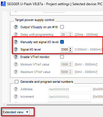

If Flasher's VTref pin is connected to a target hardware pin but Flasher still reads VTref 0, this indicates one of two things:
- The target hardware is not powered correctly
- The Flasher's VTref pin is not connected to the correct target hardware pin
Programming
Failure when programming can occur for a variety of reasons.
- Connection-related
- Programming errors can occur due to a faulty connection. See Target connection for more information on how to troubleshoot and improve target connection.
- Project-related
- Double check all project settings to ensure that they are configured as necessary. In case of doubt, consulting the developer of the target firmware application may help. During target firmware development, the developer(s) will have had to program and debug the target, most likely. As such, the developer(s) may be familiar with necessary configuration parameters to allow programming.
- Reduce the target interface speed
- The max. working target interface speed is limited by the chip design as well as the target connection setup. Long target connection wires can lower the max. working target interface speed.
- Hardware-related
- Hardware design can have an effect on programming performance and stability.
- Double check if there are components connected to the target device that may interfere with flash programming, e.g.
- hardware watch dogs
- pull-up/ pull-down resistors on target signals
- etc.
- Check the quality of the programming interface's electrical signals. See Signal Integrity for more information.
- We recommend to use reference hardware like evaluation boards, instead of custom hardware, if available. They provide a working reference that was proven to work by the respective vendor.
- If programming errors occur with custom hardware but programming is successful with an evaluation board, that indicates that a difference in hardware design is the reason for programming errors. In that case, we recommend to compare the reference hardware and custom hardware schematics for differences to determine the underlying root cause.
Verbose log
For a detailed insight into the failing operations of the programming procedure, the verbosity of U-Flash projects can be increased.
This will print additional information to the Flasher terminal (when programming is initiated from within U-Flash, this is visible in the U-Flash log).
Verbosity can be configured in the project settings under "Analysis":

For troubleshooting, we recommend to temporarily switch the verbosity to the highest level, i.e. "4: Full", and inspect the terminal output for possible failure reasons.
An increased verbosity level can have an impact of the runtime behavior of the programming procedure.
As such, we recommend to only make use of verbose output for troubleshooting purposes.
Support package
When reaching out to SEGGER support to provide help with programming failures,
providing a support package file upfront can speed up investigations, analysis and providing a fix.
U-Flash provides the option to create a support package which includes everything required by SEGGER’s engineering staff to do an analysis of a support case involving U-Flash.
In order to generate a support package, go to Help → Create support package.

As a measure to protect any sensible data, all custom data in the selected data file is being replaced with 0xFF when copied into the support package.